Measure and annotate
A mask review is full of small questions with exact answers: how far apart are these two features, what angle does this corner make, how wide is this gap, what's the radius of that fillet, how long is that meandering route? Glyph's Measure tool answers all five without leaving the canvas, and — the part that makes it more than a ruler — lets you pin any reading as a persistent dimension that stays on the drawing, survives a save, and never once appears in an exported file.
This guide starts by building a tiny scene with the Box and Circle tools, then works through every Measure mode against it: a live distance drag, angle by three clicks, gap and radius by two, then selecting one pinned dimension to delete it and clearing the rest in one step.
- Time: ~10 min
- You'll need: Glyph open on a blank document. Nothing to download, no file to load.
One orientation note before you start: the tabbed panel with Layers / Cells / Objects / Results sits on the right-hand side of the window, underneath Properties — the Box/Circle tools' size-and-position fields and the Measure tool's mode picker and pinned-dimension list all live in that same Properties area. By the end of step 3 you'll have built the scene every later step measures: two 20×10 µm bars on the default Layer 1, with their facing edges exactly 25 µm apart, and a circle further to the right with a 10 µm radius. Every number below is exact, so you can check Glyph's own readout against it as you go.
Draw the first bar with the Box tool, then dial in its exact size. Press
B(or click the Box icon in the toolbar's Draw group) to arm the Box tool, then drag out a rough rectangle anywhere on the canvas — its size and position don't matter yet, because you're about to override both. Glyph selects what you just drew and drops you back to Select, the same one-shot-then-revert behaviour every draw tool has. In the Properties panel, click Center next to Anchor so X/Y address the shape's centre rather than a corner — it stays picked for the rest of this guide. (W and H resize the shape about the point the Anchor chips (Corner / Center, at the top of the Properties panel) light, so that point stays put: on Corner the lower-left corner holds, on Center the centre does. Either way, the order you type W, H, X and Y in doesn't matter, which is why every field below goes in the same X, Y, W, H order.) Each field is labelled in µm but wants only the bare number — type-40, not-40 µm— into X,0into Y,20into W, and10into H, each confirmed withEnter. The bar is now centred at (-40, 0) µm, 20 µm wide and 10 µm tall — its right edge lands at exactly -30 µm.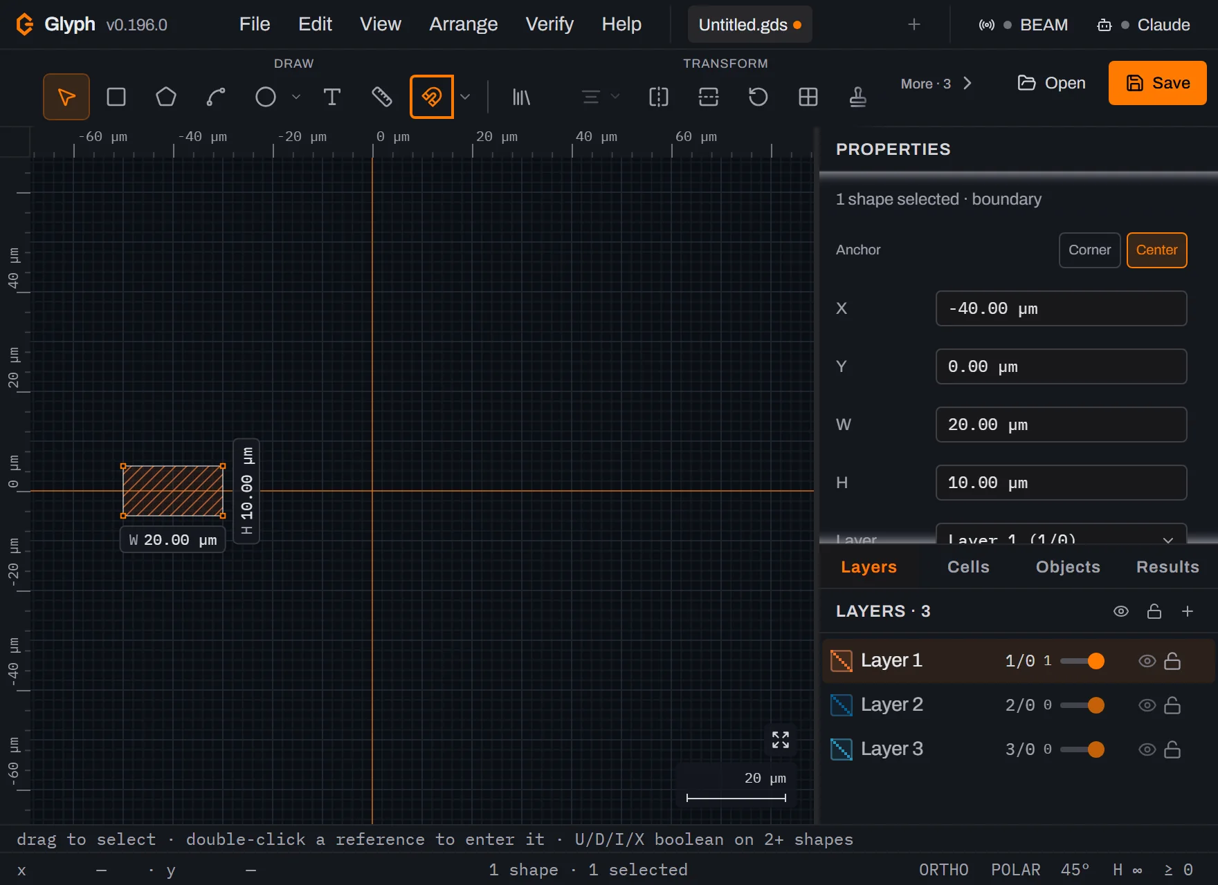 View full image
Draw the second bar the same way, 25 µm clear of the first. Press
Bagain, drag out another rough box further right, then set X to5, Y to0, W to20, and H to10. This bar is centred at (5, 0) µm, so its left edge lands at exactly -5 µm — 25 µm from the first bar's right edge, the gap every later step in this guide measures.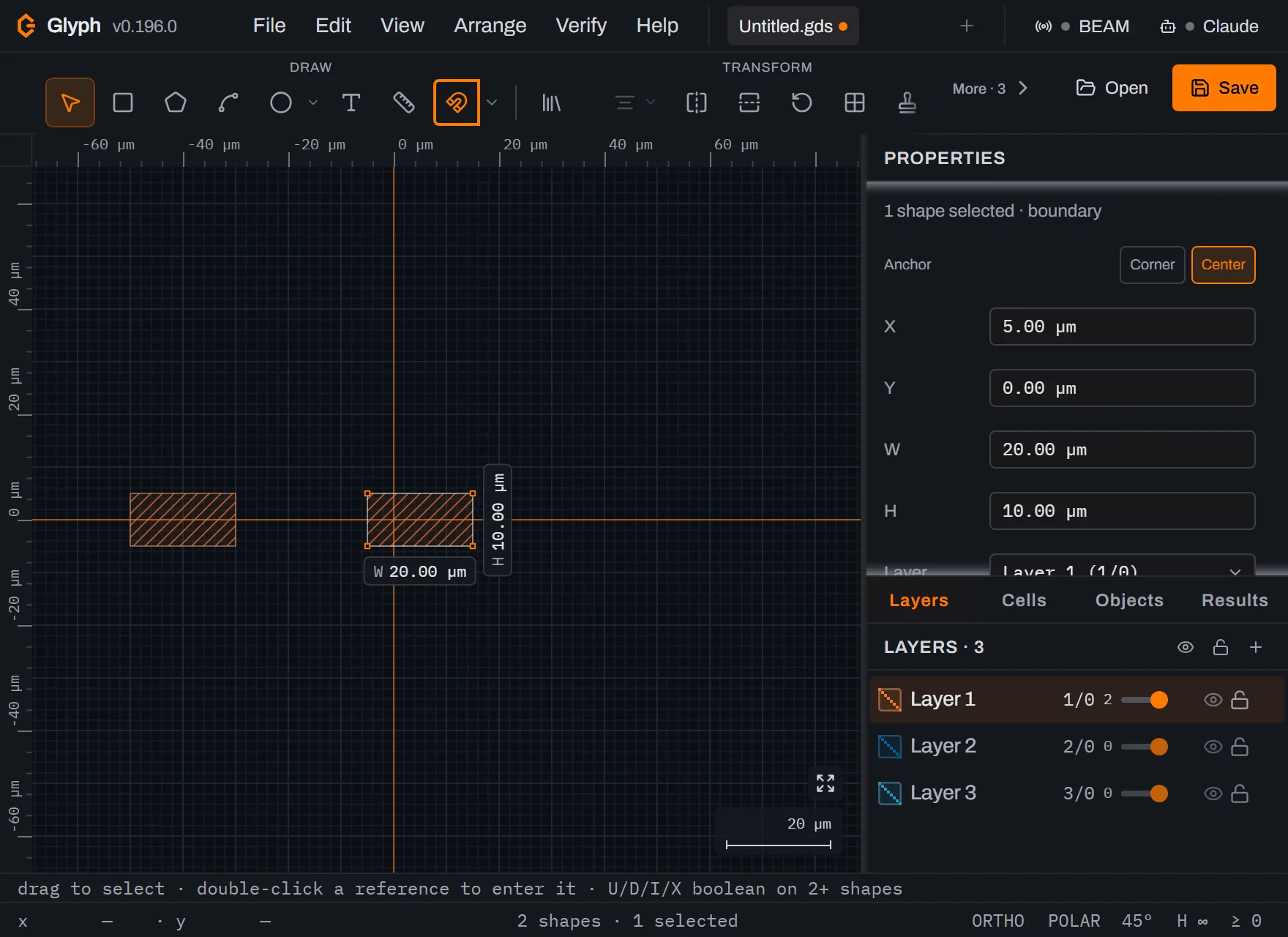 View full image
Draw the circle with the Circle tool, then set its position and diameter numerically. Press
C, then drag from roughly its centre outward to define a rough radius — again, the exact drag doesn't matter. Once it's placed and selected, a circle turns out to expose the same generic fields as any other shape: there's no dedicated radius box. Set X to60, Y to0, and both W and H to20— a circle's bounding box is its diameter in both axes, so a 20 µm square bbox centred at (60, 0) µm makes a clean 10 µm-radius circle.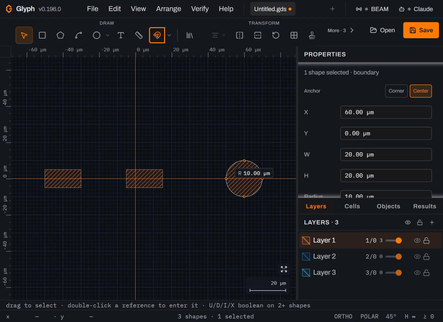 View full image
Press
Mto arm the Measure tool. The Properties panel switches from shape properties to a Measure section: five mode buttons — Distance, Angle, Gap, Radius, Chain — with Distance highlighted by default, a one-line hint under them, and a Dimensions in this cell count that starts at0with a "None yet" placeholder. In the toolbar's Draw group, the highlighted Measure (ruler) icon is the Measure toolMjust armed. The Magnet icon lit up right next to it is unrelated — that's Snap to grid, already on by default — not a second route into Measure;Mis the only way in.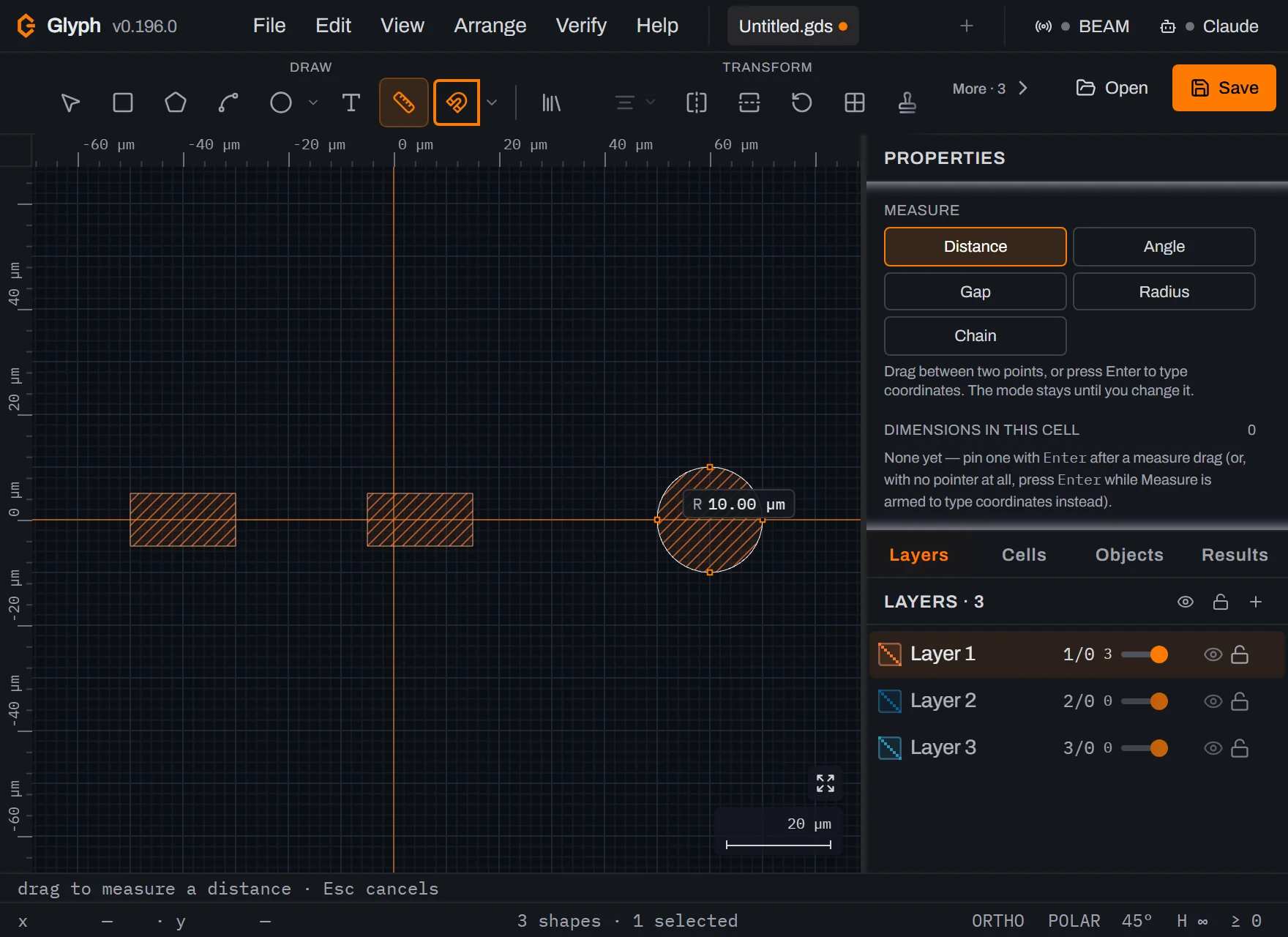 View full image
Drag between the two bars for a live readout. Starting on the left bar's right edge, drag to the right bar's left edge. As you drag, an amber line follows the cursor on the canvas and the status bar tracks the distance live, appearing right next to the shape count — not the far-right corner, which holds the ORTHO/POLAR/
Hbadges. Release on the second edge: the status bar reads25.00 µm, matching the 25 µm gap the scene was built with. (Grid snap is on by default — the magnet icon from the last step — and every coordinate in this scene is a round micrometre value, so a drag anywhere close to the bar's edge rounds to it exactly; you don't need pixel-perfect aim for the readings in this guide to come out exact.) One more thing worth knowing before the next step: a measurement doesn't select anything, so the Properties panel doesn't stay on the Measure section either — it quietly reverts to whatever shape was last selected (here, the circle from step 3, with its own X/Y/W/H fields). Step 6 brings the Measure section back by pressingMagain.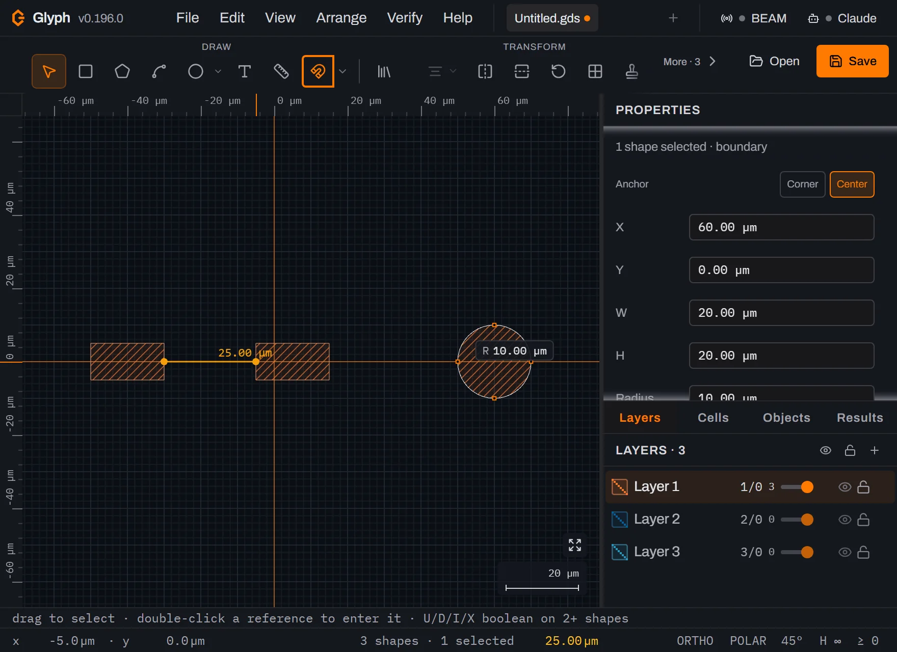 View full image
Press
Magain, thenEnter, to pin it. Like every other draw tool in Glyph, a completed measure drag drops you back to Select — that's the toolbar's active-tool label you can see change in the previous shot. The reading itself survives the switch, so pressingMre-arms the Measure tool without losing it, andEnterpins the current distance into the document as a persistent dimension. Dimensions in this cell goes from0to1, with a row readingdistance 25.00 µm. Pinned dimensions are a draw-only aid: they save with the document and reload with it, but every export format skips them, the same way it skips construction shapes. One quirk to expect on the canvas itself: the amber line and number you were just dragging are still drawn there too — that's the tool's own live readout, a separate, transient thing from the dimension you just pinned, and it stays on screen until you leave the Measure tool entirely (only switching tools clears it — changing mode does not). The next step clears it along the way.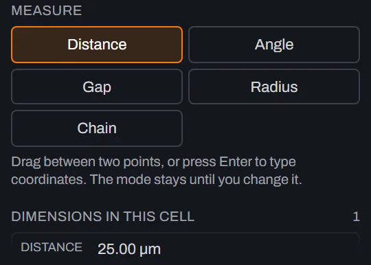
Clear the leftover readout, then switch to Angle mode. Press
Vto switch to Select — this is what actually clears the live readout from step 5, since only a tool switch does that, notEscape— thenMto re-arm Measure, and click Angle in the mode picker. Its hint changes toThree clicks: vertex, then each ray— angle measurement is click-based, not a drag, so it never starts a distance rubber-band by accident. The mode you pick here stays until you change it again; earlier versions of this tool reset to Distance after every use, which meant three angles cost three trips back to a menu.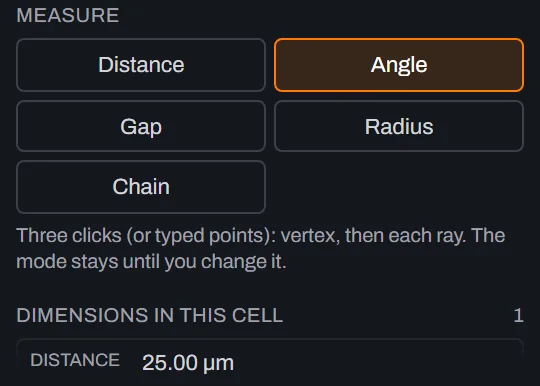
Click three points to measure an angle. Click the left bar's bottom-left corner (the vertex), then a point straight up along its left edge, then a point straight right along its bottom edge. The third click pins the dimension immediately — no
Enterneeded, since a click-collected measurement has nothing left to confirm. Because the two rays run exactly along the bar's own edges, the reading is a clean90.0°, and Dimensions in this cell reads2. On the canvas, a short arc appears right at that corner with the90.0°label offset up and toward the interior of the angle — the rays themselves trace exactly along the bar's own outline, so only the arc and the label stand out from it. At the zoom level this scene is framed at, that arc and label are small — here's the whole scene, then the same corner zoomed in: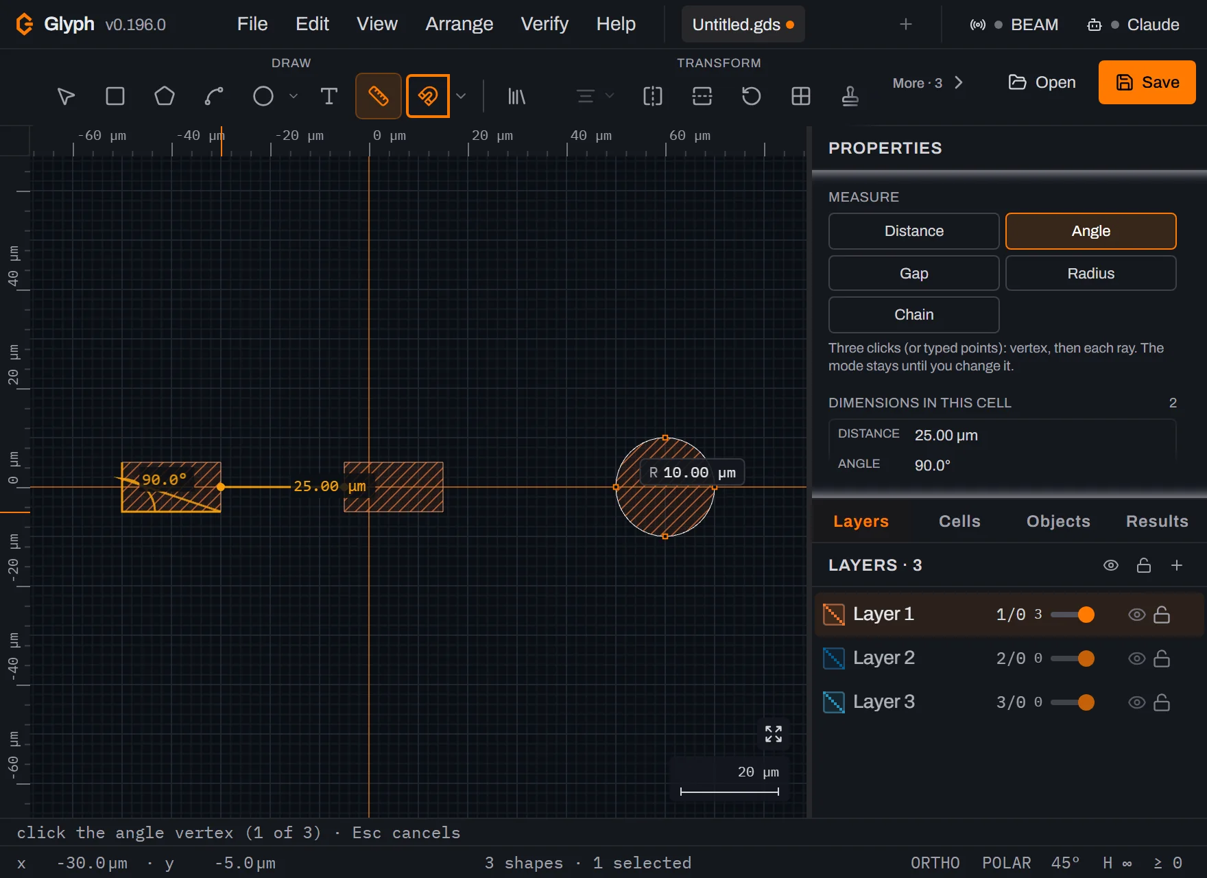 View full image
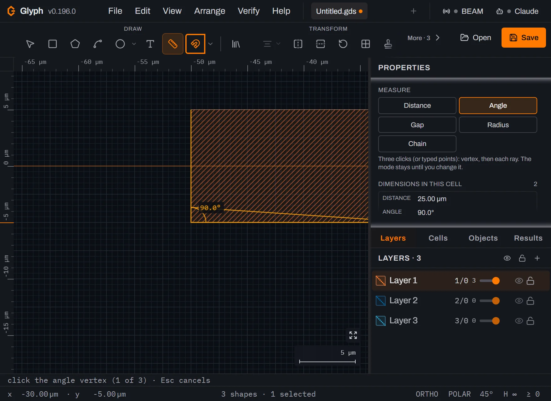 View full image
Know the other way in: . You don't have to click through the mode picker at all — this menu command arms the Measure tool and switches straight to Angle mode in one click, which is handy if you're already deep in the Verify menu checking violations. , used later in this guide, lives right below it. Press
Escto close this dropdown without picking anything — the next step continues in Gap mode, not through this menu.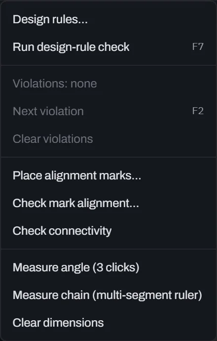
Switch to Gap mode and click the two facing edges, a little higher up. Gap is a two-click measurement, meant for exactly this: the clearance between two features, read directly off their edges rather than typed in from a ruler. Click a point near the top of the left bar's right edge, then the matching point near the top of the right bar's left edge — deliberately not the same height as your Distance drag in step 5, so this pin's label doesn't land on top of the one already there. The pin appears at once, labelled
gap 25.00 µmrather than a plain distance, so a clearance reading is never mistaken for an arbitrary measurement when you're checking it against a DRC minimum spacing. Dimensions in this cell reads3.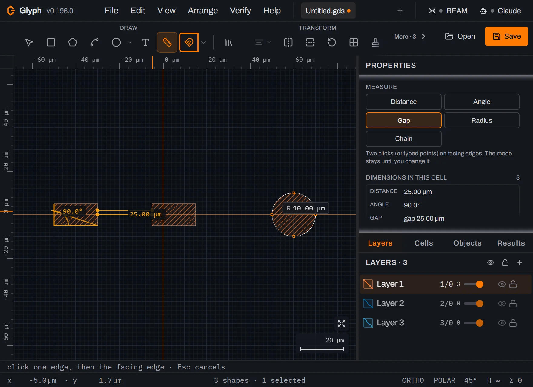 View full image
Switch to Radius mode and click the circle. Radius is also two clicks: the arc's centre first, then any point on the arc itself. The circle's centre sits right on the x-axis, at 60 µm — grid snap lands you on it exactly, so an approximate click near the middle of the circle is enough. Click there, then a point on its rightmost edge. The pin reads
R 10.00 µm, matching the circle's actual radius, and Dimensions in this cell reads4— all four modes now represented in the list.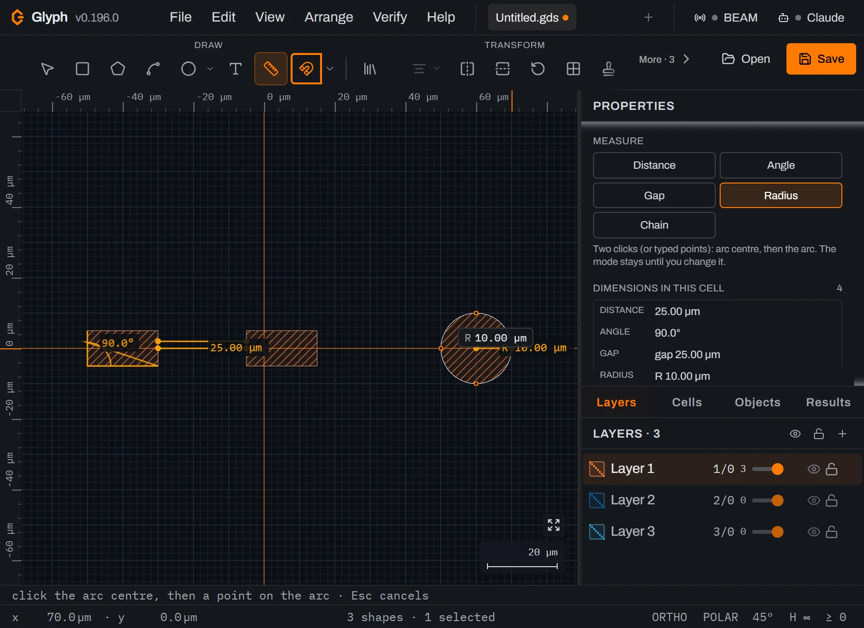 View full image
Click a row in the list to select it. Every pinned dimension is listed under Dimensions in this cell with its kind and reading. Click the
anglerow: it highlights, and a trash icon fades in on that row — hover it and it turns red, confirming which dimension you're about to delete before you click.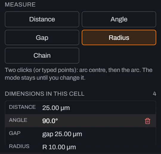
Click the trash icon to delete it. Only the angle dimension goes; the other three stay put and Dimensions in this cell drops from
4to3. This is how you clean up a single stray measurement without disturbing the rest.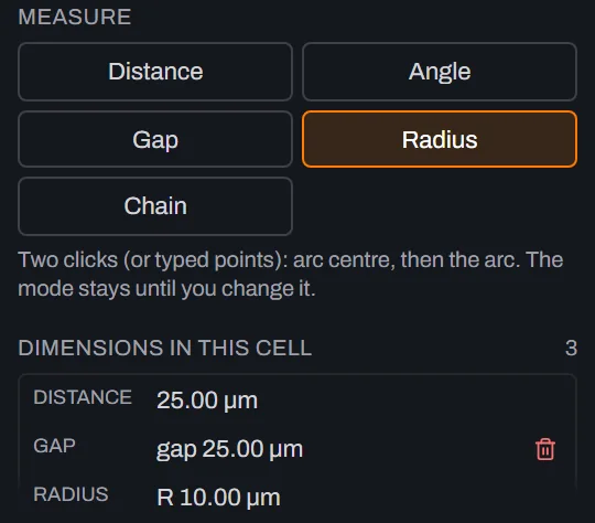
removes everything else in one step. Unlike the trash icon, this clears every dimension left in the active cell as a single undo entry — the fast path once you're done reviewing and don't want to click three separate trash icons. Dimensions in this cell reads
0again, and the "None yet" placeholder is back.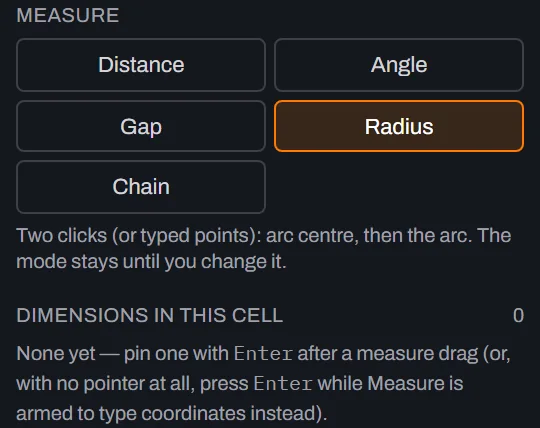
Chain rulers (multi-segment measurements)
The four modes above each answer a two-point (or three-click) question. Sometimes what you need is
a running total along a path that isn't straight — the length of a meandering trace, or a
multi-segment route around a feature — and that's a fifth mode: Chain. Press M to arm Measure
if you've left it, then click Chain in the mode picker (it's a plain click-to-select button, the
same as the other four, though it's also reachable from directly). Its hint
reads Click each vertex, Enter to finish (2+ points) — unlike Distance's single drag, Chain
collects as many clicks as you give it.
Click along the top edge of the two bars from earlier — the first bar's top-left corner, its
top-right corner, then the second bar's top-left corner — three vertices, two segments. As you
move the cursor after each click, a live rubber-band segment follows it to show where the next
click will land, and every segment already fixed shows its own running length label. Press Enter
(with at least two points clicked) to pin the whole polyline as one chain dimension. Two
labels appear on the canvas: each segment's own length at its midpoint, plus a cumulative total —
prefixed Σ — at the last vertex, so you can read either the per-leg breakdown or the whole route's
length without doing the addition yourself. Escape cancels the draft with nothing pinned, and
pressing Enter after only one click also pins nothing — a stray keypress mid-collection can't
leave a degenerate, zero-segment ruler behind.
In the Dimensions in this cell list, a chain reads as Σ followed by its total length — the
same prefix as the canvas label, so you can tell a multi-segment total apart from an ordinary
two-point distance at a glance, and it's deleted or jumped-to from its row exactly like the other
four kinds.
What you built
Two 20×10 µm bars 25 µm apart and a 10 µm-radius circle, drawn with the Box and Circle tools and placed exactly with typed Properties-panel fields rather than eyeballed drags — then a working tour of Measure's five modes against that scene: a 25.00 µm distance pinned with a drag and Enter, a 90.0° angle pinned with three clicks (reachable two ways — the mode picker or ), a gap 25.00 µm reading between two facing edges, an R 10.00 µm radius off the circle, and a two-segment Σ chain along the bars' top edge. You also saw both ends of dimension housekeeping: deleting one from its row, and clearing everything left with . Any of these readings would have exported to nothing — GDS, SVG, every writer in Glyph iterates a cell's shapes, and a Dimension isn't one.
Next steps
Read Measuring for the full reference on all five modes and how pinned dimensions behave across undo, tabs and autosave. If you're chasing a spacing number for fabrication rather than just checking it by eye, Design rule check runs the same kind of measurement automatically across an entire layer. Every shortcut used above — M, B, C and V included — is listed in Keyboard shortcuts. Then open the editor and measure something real.