Export to your toolchain
Glyph's own format is GDSII, but the rest of a group's toolchain often isn't: a collaborator's tool reads CIF, a foundry wants a KLayout layer-properties file, a mechanical CAD package wants DXF, a newer flow expects OASIS. This guide builds a small two-cell hierarchical design from a blank document, sends it out to each of those formats, exports a layer map, and is honest about what every interchange format keeps and what it quietly can't.
- Time: ~14 min
- You'll need: Glyph open on a blank document, and a plain-text editor (Notepad, VS Code, TextEdit — anything that isn't GDS-aware) to peek inside a couple of the exported files partway through. Nothing to download beforehand — every format below is one Glyph can also read back in, though this guide only proves that round trip for the CIF, in step 15.
Name and save it — . Every filename the rest of this guide shows — including every toast — only makes sense once the document actually has one; a truly blank document is called
Untitled.gdsuntil you save it. Open (or pressCtrl+Shift+S). In Chrome or Edge this opens a native Save dialog pre-filled withUntitled.gds; replace theUntitledpart withchip-demo(Glyph keeps the.gdsextension) and pick a folder. Firefox and Safari don't implement that dialog: there,Save as…downloads the file immediately under whatever name the document already has — on a fresh document that's stillUntitled.gds, so rename the downloaded file tochip-demo.gdsyourself if you want it to match the rest of this guide (the bytes are identical either way). The toast readsSaved as chip-demo.gds.
Trim to two layers — delete
Layer 3. A blank document starts with three default layers; this design only ever uses two. Click the Layers tab, hover theLayer 3row, and click its trash-can icon at the right end — Glyph asks you to confirm ("Delete Layer 3 and all shapes on it? You can undo this."), so click Delete. The panel now lists onlyLayer 1andLayer 2, proof the deletion actually happened.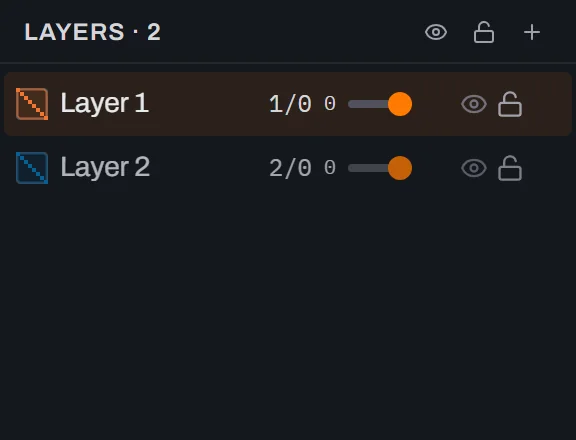
Create the
PADcell. Click the Cells tab, click the + button in its header, typePAD, and press Enter. A new row appears belowTOP:TOPis the cell your document starts in, andPADis empty for now and sits at the same level because nothing uses it yet.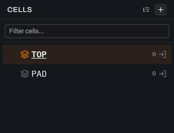
Enter PAD and draw the 20 µm outer pad on Layer 1. Click the arrow icon at the right end of the
PADrow (or double-click the row) to enter it — the breadcrumb at the top-left of the canvas now readsTOP (top) › PAD. Layer 1 is already the current layer, so arm the Box tool (the square icon in the toolbar, shortcutB) and drag out a rough square near the centre — you can't drag an exact 20 × 20 µm, and you don't need to. With the box still selected, type the real numbers into the Properties panel, which is authoritative. W and H resize the shape about the point the Anchor chips (Corner / Center, at the top of the Properties panel) light, so that point stays put: on Corner the lower-left corner holds, on Center the centre does. Either way, the order you type W, H, X and Y in doesn't matter. Anchor stays on Corner (the default), so type W20, then H20, then X-10, then Y-10— X and Y land as the box's lower-left corner. The status bar reads1 shape · 1 selected, and the Properties panel's Layer row confirmsLayer 1 (1/0).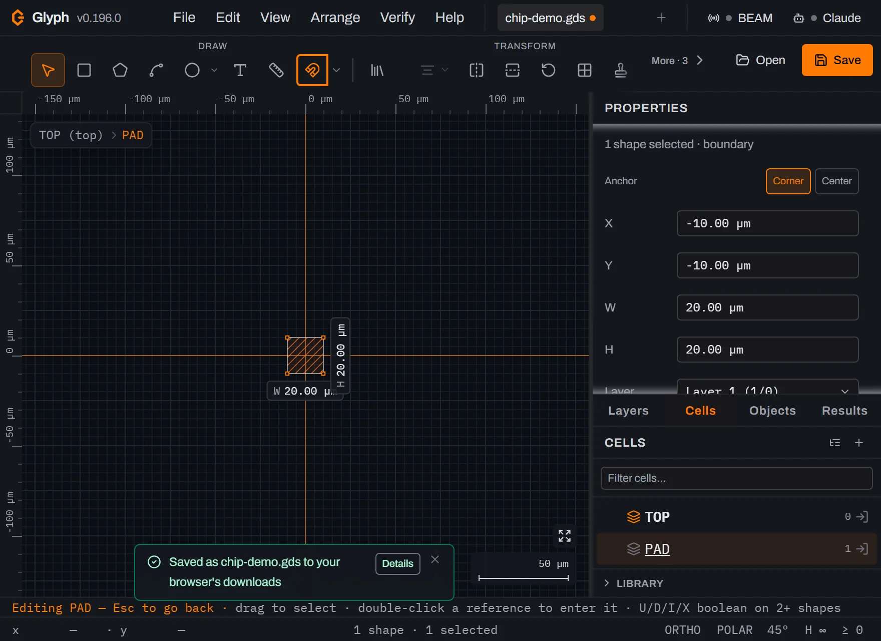 View full image
Switch to Layer 2 and draw the 8 µm inner alignment square. Click the Layers tab and click the
Layer 2row so it becomes the current layer — the highlighted row is the one new shapes land on. Arm the Box tool again (Glyph's draw tools are one-shot: a committed box reverts to Select, so a second drag without re-arming would silently marquee-select instead of drawing) and drag a rough square centred on the same origin, inside the pad. Size it the same way: W8, H8, X-4, Y-4. The Properties panel's Layer row now readsLayer 2 (2/0), and the status bar reads2 shapes · 1 selected.PADis done — a 20 µm pad with an 8 µm alignment square nested inside it, both centred on the cell's own origin.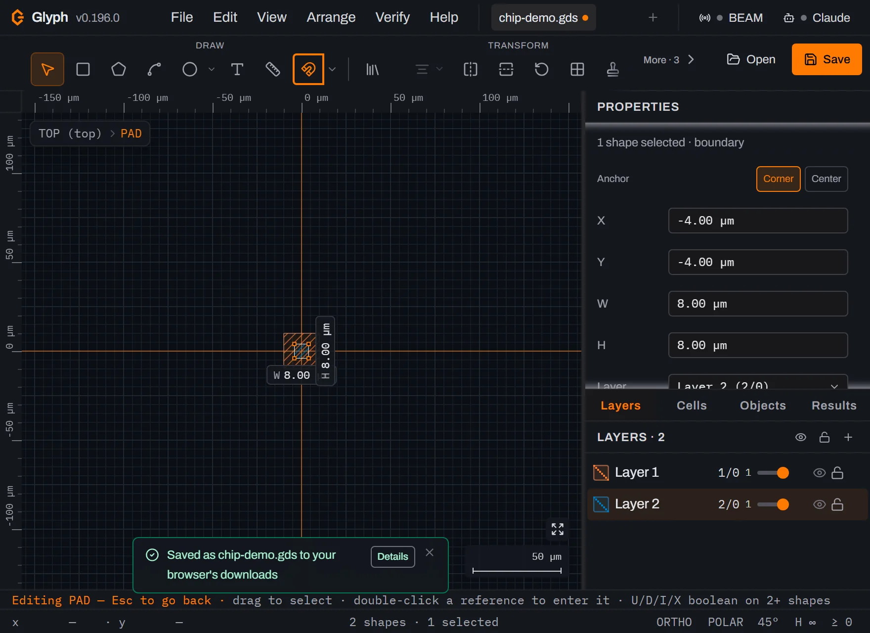 View full image
Back in TOP, hover the
PADrow to find the insert-instance icon. ClickTOP (top)in the breadcrumb to go back up. In the Cells panel, hover thePADrow: a small stacked-sheets icon already sits at the row's LEFT end at all times — that's just the row's own cell-type icon, not a control, and hovering it does nothing. What hovering the row DOES reveal is a fresh set of icons at the RIGHT end, and the one among them that looks like stacked cubes is Insert cell instance (SREF) — that's the one the next step clicks, not the icon on the left.
Place two instances of PAD roughly 200 µm apart. Click the stacked-cubes icon, then click once on the canvas about 100 µm left of the origin. A copy of the pad appears — except it isn't a copy, it's a reference (GDS calls it an SREF): a pointer to
PADplus a position. The instantTOPreferencesPADonce,PADstops being a root row in the Cells panel — the tree only lists cells nothing else uses, so it now lives nested one level underTOP. Click the disclosure triangle on theTOProw to reveal it there, hover that nestedPADrow the same way, click the same stacked-cubes icon again, and click once more about 100 µm right of the origin. The status bar reads0 shapes · 2 refs:TOPitself still holds no geometry of its own, only two placements ofPAD. The Cells panel now shows the full story at a glance —TOP's own row reads0·2(0 shapes of its own, 2 references), and the nestedPADrow reads2with a×2badge beside it (2 shapes inside it, used twice).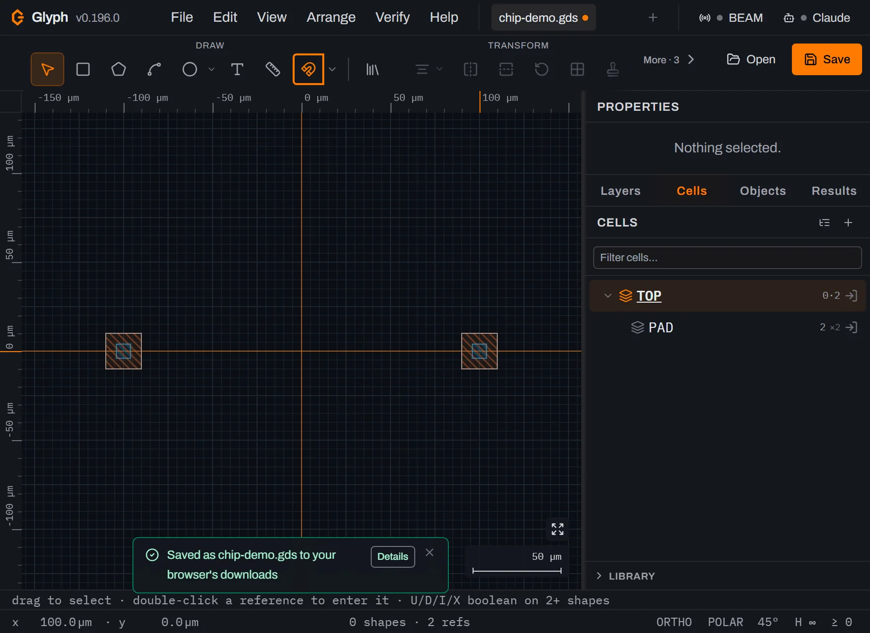 View full image
Find the interchange formats — . Six formats live in one flyout: Export SVG…, Export PNG…, Export DXF…, Export CIF…, Export OASIS…, Export EPS…, then Export figure… and Export per layer… below a divider. Glyph's own GDS is deliberately NOT in this list — it isn't an interchange format to export to, it's the native format
Ctrl+Salways writes (step 14 below). ( — the command you already used in step 1 — reaches all seven writable formats in one native "Save as" dialog: these same six interchange formats, plus GDS itself. Type any of the seven extensions and that picks the format. This guide uses the dedicatedExportcommands for the six interchange formats instead, because each one names its destination format outright rather than asking you to spell an extension correctly.) The same flyout also carries Export connectivity…, which this guide doesn't use: it writes a port↔port JSON graph of component instances and connectors, not geometry, so it's a bridge for MINT/Fluigi-class tooling rather than another format your mask-layout toolchain reads.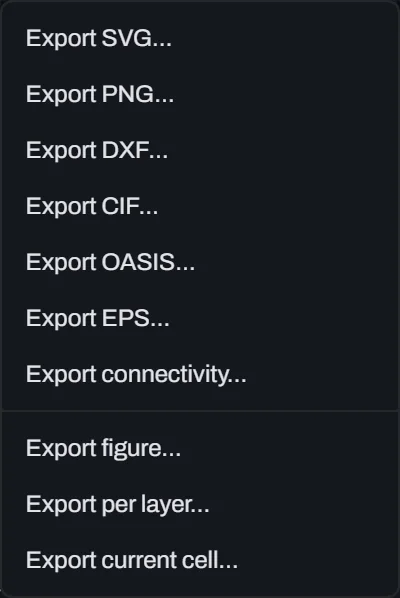
Export CIF… Click it. No GLYPH dialog opens — no options to choose. Your BROWSER may show its own Save dialog (Chrome/Edge, pre-named
chip-demo.cif, letting you pick the folder) or drop the file straight into your Downloads folder (Firefox/Safari), the same split as step 1's Save As. A toast confirmsExported chip-demo.cifeither way, and a second one lists what CIF cannot carry (magnified references are flattened, and text keeps only its string); it stays until you close it, and its Details button shows the full list. You'll need this file again in step 15 — remember which one you got. To peek inside, open the downloaded file in your plain-text editor. CIF is genuinely plain text: the file opens with a header comment reading exactly(CIF written by Glyph);, then your two layers asL1D0_LAYER1/L2D0_LAYER2(the layer and datatype, then the name the way KLayout's own CIF writer spells it: upper case, spaces dropped), each followed by a(CleWin: …)comment carrying the name as typed and the colour, then the hierarchy preserved as real symbol calls —TOPcallsPADtwice, it isn't flattened into loose polygons.
Export OASIS… Same flyout, same one-click write, same Chrome/Edge-native-dialog-vs-Firefox/Safari-Downloads-folder split as the CIF export above. The toast reads
Exported chip-demo.oas. OASIS (SEMI P39) is a compact binary format — the file starts with the 13-byte magic every OASIS reader checks for: the 11-character token%SEMI-OASISfollowed by a CRLF (\r\n, the remaining 2 bytes). It's built for the huge cell counts a modern mask can have.
Export DXF… Same download behavior again. The toast reads
Exported chip-demo.dxf. It's an AutoCAD R2000 drawing, 1 drawing unit = 1 nanometre, with each Glyph cell becoming a DXF block — useful the moment someone on the team is working in mechanical CAD rather than a mask editor.
A layer map lives somewhere else — . A layer's NAME, colour and fill pattern are presentation, not geometry, so exporting that palette is a separate flyout from the geometry formats above: Save layer setup…, Load layer setup…, then Import foundry layer map…, Export layer map (.lyp)…, Export layer map (.csv)….
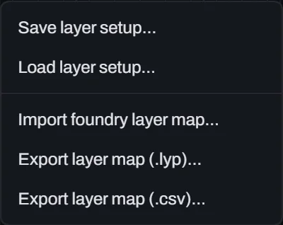
Export layer map (.lyp)… Click it. Same download behavior as every export above, and a toast confirms
Exported chip-demo.lyp— a KLayout layer-properties file. That file carries your original layer names and colours in a form OTHER TOOLS read, in KLayout's own portable convention. The geometry formats above carry names too, each in its own way (CIF in the layer token, OASIS inLAYERNAMErecords, DXF in the layer name), but CIF's colours ride only in comment records other tools ignore (see step 16), and GDSII itself keeps neither. Open the downloaded.lypin your plain-text editor and you'll find<fill-color>#EE7733</fill-color>for Layer 1 and<fill-color>#0077BB</fill-color>for Layer 2 — the same two hex values Glyph's default palette assigned when you created those layers. Load it back with (or KLayout's own "Load Layer Properties") on the other end.
The honesty step:
Ctrl+Sstill only ever writes GDS. Press it (or click the Save button). Because step 1 already saved this document aschip-demo.gds, Chrome and Edge now hold a handle to that exact file:Ctrl+Sthere writes straight back into it, and the toast readsSaved chip-demo.gds— no "as", because it's the same file rather than a new one. Firefox and Safari can't hold that kind of handle, so thereCtrl+Srepeats the full Save-as download every time, and the toast readsSaved as chip-demo.gdsinstead — which is what the screenshot below shows. Either way, the last four exports wrote CIF/OASIS/DXF/.lyp, and none of that changes whatCtrl+Swrites: only plain GDSII. Glyph deliberately never letsCtrl+Sbind to one of those other formats: CIF flattens magnified references and strokes paths, DXF has no datatype field, so Glyph folds the pair into each layer's name, OASIS drops bitmaps and construction shapes and squares off a round GDS path — each is lossy in a specific, documented way, so silently overwriting one on every keystroke would quietly throw away information your working document still has. Your master file stays GDS; every format above is something you generate FROM it, on purpose, each time.
Prove the round trip — open the CIF back up. Click the + to start a new blank tab. This matters because Open doesn't create a tab of its own — it loads into whichever tab is currently active — so without clicking + first, Open would overwrite
chip-demo.gdsright there in its own tab. With the new blank tab active, click Open and pick thechip-demo.cifyou exported in step 9 (wherever your browser's Save dialog or Downloads folder put it). It loads into that new tab, which renames itself tochip-demo.cifthe moment the file is parsed — so you end up with exactly two tabs,chip-demo.gdsandchip-demo.cif, never a stray leftoverUntitled.gds. The Cells panel confirms the hierarchy survived:TOPstill holdsPADnested underneath it, used twice, exactly as it was before you ever wrote a CIF byte.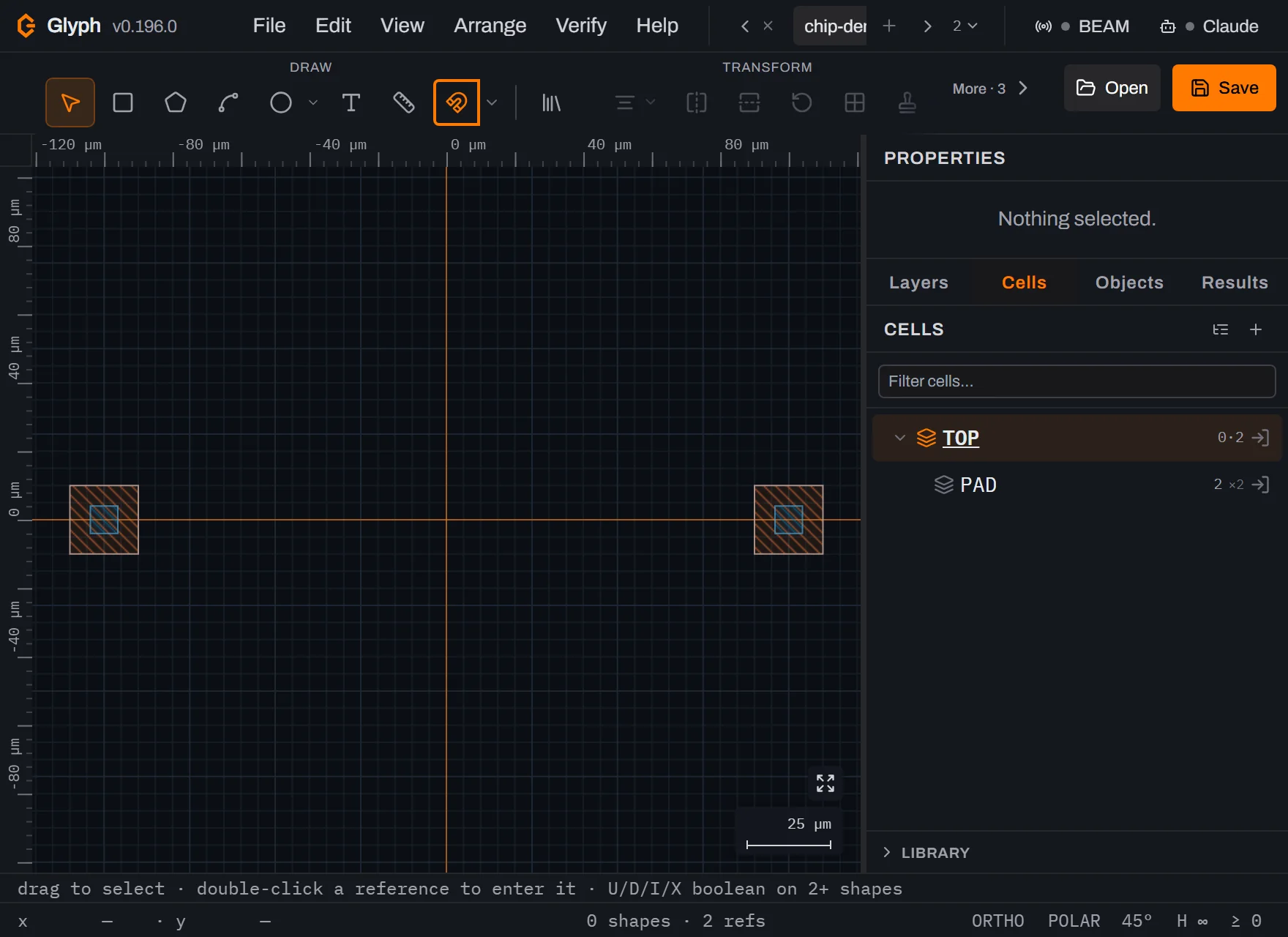 View full image
Both layers came back too — names and all. Switch to the Layers tab: two layers, still
1/0and2/0, and still namedLayer 1andLayer 2. The name rode in the layer token itself (L1D0_LAYER1, the form KLayout's own CIF writer uses), and Glyph's reader takes the exact spelling back from the(CleWin: …)comment beside it, soLayer 1does not come back asLAYER1. A layer that never had a name is written as the bareL1D0and reads back asLayer 1. The small shape count beside each row reads0, with a dim↳— that count is per the ACTIVE cell, and you're looking at it whileTOPis active, which holds no shapes of its own, only the twoPADreferences; hover it and it says the shapes are in other cells. Step intoPADand each row reads1, the one square on that layer. The canvas (previous screenshot) shows the colours came back too, the SAME orange and blue as before the round trip — and that is not a default-palette coincidence: since v0.107.0 Glyph writes each layer's fill/edge colour into the CIF as an inert(CleWin: …)comment record, and its own reader restores it on reopen. The catch is the audience: those comment records are Glyph's (and CleWin's) convention — KLayout and most other CIF tools ignore them, so the colour and the exact spelling survive a Glyph→Glyph round trip, while KLayout keeps only the token (it readsL1D0_LAYER1as layer 1/0 namedLAYER1). The.lypfrom step 13 remains the portable way to hand names AND colours to another tool.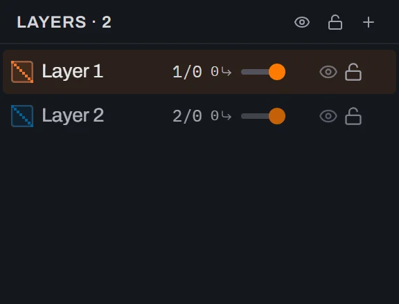
What you built
A two-cell design — a PAD cell with a 20 µm pad on Layer 1 and an 8 µm alignment square on Layer 2, placed twice in TOP — drawn from a blank document, then sent out to five files: a CIF, an OASIS and a DXF version of the same layout, a KLayout .lyp layer map carrying the names and colours in a form other tools actually read, and a confirmation that plain Ctrl+S never drifts off GDS no matter what you've exported in between. You also proved the CIF round trip yourself — reopened it in a fresh tab and watched the hierarchy, the layer numbers and the layer names come back — the names ride in the CIF layer token, which other CIF tools read too, and the colours in Glyph's own CIF comment records, a convention only Glyph and CleWin honour.
The pattern generalises: pick the format your teammate or tool actually reads, export it from , and keep treating the .gds your Ctrl+S keeps writing as the one file you never have to re-derive anything from.
Next steps
Open and save GDS files covers the full save/export picture, including what a plain GDS round trip preserves that these other formats don't. Layers covers the palette this guide split off into its own .lyp file. For the two comparisons this guide only touched in passing, see the reference pages GDS vs OASIS and DXF vs GDS. Cells and hierarchy explains what "flattening" a reference means for the formats that do it. Then open the editor and export the design you actually need to hand off.